RSS

COMPUTER NUMERICAL CONTROL (CNC)

Numerical control (NC) is a flexible method of automatically controlling machines through the use of numerical values. Numerical control enables an operator to communicate with machine tools through a series of numbers and symbols. Many languanges exist for writing an NC program, but the one most used is called automatically programmed tools (APTs).

The programming of NC machines can be categorized into two main areas : point-to-point programming, and contour programming.

  • Point-to-point programming involves straight-line movements. The point where each hole is to be located is identified using X and Y coordinates. After each hole is drilled, the machine is instructed to move to the next point where a hole is to be drilled, and so on. The holes are drilled sequentially until program is completed.
  • Contour (also known as continuous path) programming involves work like that produced on milling machines, where the cutting tool is in contact with the workpiece as it travels from one programmed point to the next.

Computerized numerical control (CNC) was introduced to replace the punched tape and hard-wired machine control of older NC units. CNC introduced a new flexibility into the manufacturing industry as the microprocessor-based control equipment brought features to NC machines, such as:

  • Improved program mass storage, disk instead of punched tape
  • Ease of editing programs
  • Possibility of more complex contouring because of the computer’s capability for mathematical manipulation
  • Reusable machine pattern, which could be stored and retrieved as required
  • Possibility of plantwide communication with many peripheral devices

CNC VIDEO


Leave a comment

Posted by on May 11, 2014 in Industrial Electronics


NUMBER SYSTEMS AND CODES

Image

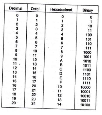
The decimal system has a base of 10. The base of a number system determines the total number of different symbols or digits used by that system. The value of a decimal number depends on the digits that make up the number and the place value of each digit. In the decimal system the first position, starting from the furthest right position, is 0; the second is 1; and so on up to the last position. The weighted value of each position can be expressed as the base raised to the power of the position.

Image

 The binary numbering system is the basis of all digital system. Two states exist in digital equipment, an ON state which is representative of one (1), and an OFF condition which is representative of zero (0). The decimal equivalent of a binary number is calculated in a manner similar to that used for a decimal number. The weighted value is 2 raised to the power of the position.

ImageImage

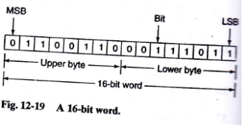
Each digit of a binary number is known as a bit. Bit can also be grouped within a word into bytes. The least significant bit (LSB) is the digit that represents the smallest value, and the most significant bit (MSB) is the digit that represents the largest value.

Image

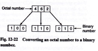
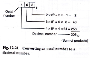
The octal numbering system, a base 8 system, is often used in microprocessor, computer, and programmable controller systems because 8 data bits make up a byte of information which can be addressed by the PLC user or programmer.

ImageImage

The hexadecimal (hex) number system provides even shorter notation than octal. Hexadecimal uses a base of 16. It employs 16 digits: numbers 0 through 9, and letters A through F, with A through F being substituted for numbers 10 through 15, respectively.

Image

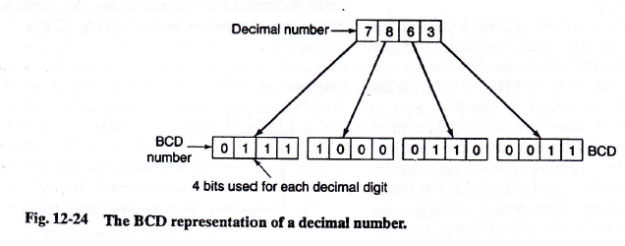
The binary coded decimal (BCD) system provides a convenient means to handle large numbers that need to be input to or output from PLC. The BCD system represents decimal numbers as patterns of 1s and 0s. This system provides a means of converting a code readily handled by humans (decimal) to a code readily handled by the equipment (binary). The BCD code employs 4 binary bits, with the weights of 1, 2, 4, and 8, to represent each numeral in the decimal system.

Image

 
Leave a comment

Posted by on May 11, 2014 in Industrial Electronics


TYPES OF PROCESSES

The types of processes carried out in modern manufacturing industries can be grouped into three general areas, in terms of the kind of operation that takes place, as :

  • Continuous process
  • Batch production
  • Individual products production

CONTINUOUS PROCESS

A continuous process in one in which raw materials enter one end of the system and the finished product comes out the other end of the system; the process itself runs continuously.

Image

BATCH PRODUCTION

In batch processing, there is  no flow of product material from one section of the process to another. Instead, a set amount of each of the inputs to the process is received in a batch, and then some operation is performed on the batch to produce a finished product or an intermediate product that needs further processing.

Image

INDIVIDUAL PRODUCTS PRODUCTION

The individual product production process is the most common of all processing systems. The item being produced may be required to be bent, drilled, welded, and so on, at different steps in the process.

Image

The control of machines or processes can be divided into the following categories :

  • Electromechanical control
  • Hardwired electronic control
  • Programmable hardwired electronic control
  • Programmable logic control (PLC)
  • Computer control

Possible control configurations include individual control, centralized control, and distributed control.

Individual control is used to control a single machine. This type of control does not normally require communication with any other controllers.

Image

Centralized control is used when several machines or processes are controlled by one central controller. This control layout utilizes a single large control system to control many diverse manufacturing processes and operations.

Image

Distributive control is handled by a dedicated control system for each machine. Each dedicated control is totally independent and could be removed from the overall control scheme. It involves two or more computers communicating with each other to accomplish the complete control task.

Image

 
Leave a comment

Posted by on May 11, 2014 in Industrial Electronics


COUNTERS

Counters are device that will receive a string of count pulses from a machine operation and perform an output function based on a number of counts predetermined by the user. Most counters, like timers, can have interval and delay operation.

  • Interval operation means that a load will be actuated when the unit is counting.
  • Delay operation means that a load will be actuated at the end of the counting cycle.

In electronics, counters can be implemented quite easily using register-type circuits such as the flip-flop, and a wide variety of classifications exist:

  • Asynchronous (ripple) counter – changing state bits are used as clocks to subsequent state flip-flops
  • Synchronous counter – all state bits change under control of a single clock
  • Decade counter – counts through ten states per stage
  • Up/down counter – counts both up and down, under command of a control input
  • Ring counter – formed by a shift register with feedback connection in a ring
  • Johnson counter – a twisted ring counter
  • Cascaded counter
  • Modulus counter

ASYNCHRONOUS COUNTER

An asynchronous (ripple) counter is a single d-type flip-flop, with its J (data) input fed from its own inverted output. This circuit can store one bit, and hence can count from zero to one before it overflows (starts over from 0). This counter will increment once for every clock cycle and takes two clock cycles to overflow, so every cycle it will alternate between a transition from 0 to 1 and a transition from 1 to 0. The result is called a ripple counter, which can count to 2n – 1 where n is the number of bits (flip-flop stages) in the counter.

SYNCHRONOUS COUNTER

In synchronous counters, the clock inputs of all the flip-flops are connected together and are triggered by the input pulses. Thus, all the flip-flops change state simultaneously (in parallel). Synchronous counters can also be implemented with hardware finite state machines, which are more complex but allow for smoother, more stable transitions.

In mechanical counter, every time the actuating lever is moved over, the counter adds one number, and the actuating lever returns automatically to its original position.

The electromechanical counter is constructed so that it is similar to the electromechanical reset timer, except that the synchronous motor of the timer is replaced by a solenoid-operated pawl feed count motor.

Most solid-state counters can count up, count down, or be combined to count up and count down. An up-counter will count up or increment by 1 each time the counted event occurs. A down-counter will count down or decrement by 1 each time the counted event occurs.


Source :

Petruzella, Frank D. 1996. Industrial Electronics. Singapore: McGraw Hill.

http://en.wikipedia.org/wiki/Counter

http://www.ni.com/white-paper/14496/en/

 
Leave a comment

Posted by on May 11, 2014 in Industrial Electronics


MOTOR SPEED CONTROL

In general, motor speed control can be classified into four areas :

  1. Multispeed motors
  2. Variable speed drivers for induction and synchronous motors
  3. Wound rotor induction motor control
  4. DC motor controllers

MULTISPEED MOTORS

Some motors are designed to operate at two, three, or four separate designated speeds. The speed of an induction motor depends on the number of poles built into the motor and the frequency of the electrical power supply. Multispeed motors are available up to 500 hp, and are very reliable, but have several drawbacks. Multispeed motors are often found in applications such as ventilating fans and pumps. There are two main types : the separate winding motor and the consequent pole motor.

The separate winding motor uses two or more windings that are electrically separate from each other. Each winding can deliver the motor’s horsepower at the rated speed.

The consequent pole motor uses a special winding that can be reconnected, using contactors, to obtain different speeds. There are types of consequent pole motors : constant horsepower, constant torque, and variable torque.

VARIABLE SPEED DRIVES

A varible speed drive is used to provide continuous range process speed control (as compared to discrete speed control as in multispeed or pole changing motors). Variable speed drives may be referred to by a variety of names, such as adjustable speed drives. adjustable frequency drives, and variable frequency inverters. An electrical variable speed drive is an electrical system that is composed of the motor, drive controller, and operator’s controls (either manual or control).

The drive controller is an electronic device that can control the speed, torque, horsepower, and direction of an AC or DC motor. Common control functions associated with adjustable speed drives include :

  • Preset speed that refers to one or more fixed speeds at which the drive will operate.
  • Base speed that is the manufacturer’s nameplate rating where the motor will develop rated horsepower at rated load and voltage.
  • Speed range extends from the speed minimum to maximum at which a motor must operate under constant or variable torque load conditions.
  • Speed regulation is the numerical measure, in percent, of how accurately the motor speed can be maintained.
  • Regenerative control contains the inherent capability and/or power semiconductors to control the flow of power to and from the motor.
  • Four-quadrant operation that refers the four combinations of forward and reverse rotation and forward and reverse torque of which a regenerative drive is capable. The four combinations are : forward rotation/forward torque (motoring), forward rotation/reverse torque (regeneration), reverse rotation/reverse torque (motoring), and reverse rotation/forward torque (regeneration).


WOUND ROTOR AC MOTOR DRIVES

Wound rotor motor is a specially constructed motor that can accomplish speed control. The motor rotor is constructed with windings that are brought out of the motor through slip rings on the motor shaft. These windings are connected to a controller, which places variable resistors in series with the windings.


Leave a comment

Posted by on May 11, 2014 in Industrial Electronics


MAGNETIC MOTOR STARTERS

The basic use for the magnetic contactor is for switching power in resistance heating elements, lighting, magnetic brakes, or heavy industrial solenoids.

  • Contactors can also be used to switch motors if separate overload protection is supplied.
  • magnetic starter is a contactor with an overload relay phisically and electrically attached.

The difference between contactor and magnetic motor starter is the use of overload relays on the motor starter. The purpose of overload protection is to protect the motor windings from excessive heat resulting from motor overloading.

External-overload protection devices, which are mounted in the starter, attempt to stimulate the heating and cooling of a motor by sensing the current flowing to it. The goal is to protect the motor from overheating.

Magnetic-overload relays operate on the magnetic action of the load current that is flowing through a coil.

Thermal-overload relays uses a heater connected in series with the motor supply.This type of protection is very effective because the heater closely approximates the actual heating within the windings of the motor and has a thermal “memory” to prevent immediate reset and restarting. There are two common types : the bimetallic type, which utilizes a bimetallic strip and the melting alloy type, which utilizes the principle of heating solder to its melting point.

Electronic-overload relay uses a current transformer and electronic circuitry.

Some advantages of solid-state electronic overload relays oer thermal-overload types are the following :

  • No buying, stocking, installing, or replacing of heater coils
  • Reduction in the heat generated by the starter
  • Energy savings through the elimination of heater coils
  • Insensitivity to temperature changes in the surrounding environment
  • High repeat trip accuracy
  • Easily adjustable to a wide range of full-load motor currents
 
Leave a comment

Posted by on May 11, 2014 in Industrial Electronics


TIMING RELAY

Timing relays are conventional relays that are equipped with an additional hardware mechanism or circuitry to delay the opening or closing of load contacts. The difference between timing relay and contact relay is that the contacts of the timing relay delay changing their position when the coil is energized or deenergized.

pneumatic (air) timing relay uses mechanical linkage and an air-bellows system to achieve its timing cycle. The bellows design allows air to enter through a needle valve at a predetermined rate to provide the different time-delay increments and to switch a contact output. Pneumatic timing relays are adjustable over a wide range of time periods, they are relatively unaffected by temperature or voltage variations, and they have good repeat accuracy.

Figure 1 Pneumatic Timing Relays

solid-state timing relay uses electronic circuitry to achieve its timing cycle. The length of the time delay can be set by adjusting a control knob or potentiometer located on the front of the timer. Timing indication is provided by an LED that flashes during timing, glows steadily after timing, and is OFF when the timer is deenergized.

Figure 2 Solid-state Timing Relay

 
Leave a comment

Posted by on May 11, 2014 in Industrial Electronics


DIRECT CURRENT GENERATORS

Direct current generator is mainly produced by solid state rectifier diodes.

The two slip rings of the AC generator have been replaced by a single segmented rotating contact called a commutator. Commutator acts like a mechanical switch or rectifier to automatically convert the generated AC voltage into a DC voltage. Most DC generators use electromagnetic field coils rather than permanent magnets. The direct current used to energize the field windings is called  the exciting current.

Direct current generators are classified according to the method by which current supplied to these field coils. The two major classifications are separately excited and self-excited generator types.

  • A DC generator that has its field current supplied by an outside source is called a separately excited generator
  • The incovenience of a separate DC source for field excitation led to the development of self-excited generators. Self-excited generator use part of the generated current to excite the field.

In a shunt generator, the shunt field windings are connected in parallel with the amature. The shunt field windings consist of many turns of relatively small wire and actually use only a small part of the generated current.

compound generator is similar to a shunt generator, except that it has additional field coils connected in series with the armature. The compound generator was developed to prevent the terminal voltage of a DC generator from decreasing with increasing load.

 
Leave a comment

Posted by on May 11, 2014 in Industrial Electronics


MULTIMETERS

The multimeter is a combination of voltmeter, amperemeter, and ohmmeter in a single instrument. Multimeter, that is commonly known as VOM (Volt-Ohm Meter, is differentiated by two type which are analog multimeter and digital multimeter.

ANALOG MULTIMETER (AMM)

This type of a multimeter is basically a moving coil instrument. An analog multimeter will have a scale with numbers on it. When you are testing something, such as the voltage of a 12 volt car batter, a needle will move and point to how many volts that battery has (around 12 if it is fully charged). 

How to read analog multimeter (retrieved from http://www.wikihow.com/Read-a-Multimeter)

1. Set the range on your analog multimeter.

Read a Multimeter Step 1.jpg

2. Determine the value of the maximum reading. The maximum reading equals the range that you set on your dial. If you set your dial at 200 volts, then this multimeter reading is showing 200 volts.

Read a Multimeter Step 2.jpg

3. Calculate the reading at half scale. The reading at half scale equals the volt range divided by 2. If your multimeter is set to 200 volts, then this reading indicates an output of 100 volts.

Read a Multimeter Step 3.jpg

4. Calculate the reading at different points along the scale. If your range is 200 volts and your needle points to 0.72, then the reading is at 0.72 x 200, or 144 volts.

Read a Multimeter Step 4.jpg

DIGITAL MULTIMETER (DMM)

A DMM has a digital display and a function selector switch. The range selection takes place automatically.

COMPARISON BETWEEN ANALOG AND DIGITAL MULTIMETER

In analog multimeters, visual indication of changes in the reading is not good due to the effect of damping torque. Whereas in a digital multimeter, an excellent visual indication of changes in reading is acquired.

Analog multimeters are accurate, but not as much as the digital multimeter due to the magnetic effect in the coil being degraded after usage. Digital multimeters are highly accurate compared to analog.

An analog multimeter is less costly compared to the digital counterpart due to a simple construction and no power supply being required. But in the case of a digital multimeter, it is far more expensive than the analog multimeter and has a complicated construction, and also requires a power supply.

In an analog multimeter, the range has to be adjusted by the user. Whereas in a digital multimeter, the range is adjusted automatically.

In a digital multimeter, the mechanical handle can be easily rotated to tune the circuit to its peak.

Source :

http://www.brighthubengineering.com/diy-electronics-devices/94131-digital-and-analog-multimeters-which-is-best-to-use/

Petruzella, Frank D. 1996. Industrial Electronics. Singapore: McGraw Hill

 
Leave a comment

Posted by on May 10, 2014 in Industrial Electronics


MANUALLY OPERATED SWITCHES

A manually operated switch is a switch that directly controlled by hand. Type of manually operated switch are :

  • Toggle switch
  • Slide switch
  • Rocker switch
  • DIP (Dual in-line Package) switch
  • Rotary switch
  • Thumbwheel switch
  • Selector switch
  • Pushbutton switch
  • Drum switch

TOGGLE SWITCH

Toggle switches are one of the innumerable components of an electrical system with a definite purpose. In terms of electrical use, it is defined as a device that allows or bars the flow of current. Toggle switches slightly differ from normal switches in their working mechanism. It resembles a gate that has 2 parts to itself. When the gate is closed and the two parts are in contact, current flows through the system. This is the on position. When the gate is open and the two parts are detached from each other, the circuit is broken and no current flows through it. This happens in the off position.

Image

Figure 4 Toggle Switch

SLIDE SWITCH

Slide switch uses a simple slide action to produce the same connections as a toggle switch. The slide switch is often used as a mode switch to select  certain mode of operation such as HIGH and LOW.

Image

Figure 5 Slide Switch

ROCKER SWITCH

Rocker switch is often a modified slide switch. A rocker switch is an on/off switch that rocks (rather than trips) when pressed, which means one side of the switch is raised while the other side is depressed much like a rocking horse rocks back and forth. Rocker switches are used in surge protectors, display monitors, computer power supplies, and many other devices and applications.

Image

Figure 6 Rocker Switch

DIP (DUAL IN-LINE PACKAGE) SWITCH

DIP switch is a manual electric switch that is packaged with others in a group in a standard dual in-line package (DIP). DIP switches are small switch assemblies designed for mounting on printed circuit boards or inserted in a socket. Their main advantages are that they are quicker to change and there are no parts to lose.

Image

Figure 7 DIP Switch

ROTARY SWITCH

The rotary switch is often used for more complex switching operations, such as those found on oscilloscopes and multimeters. A rotary switch consists of a spindle or “rotor” that has a contact arm or “spoke” which projects from its surface like a cam. Rotary switches were used as channel selectors on television receivers until the early 1970s, as range selectors on electrical metering equipment, as band selectors on multi-band radios, etc.

Image

Figure 8 Rotary Switch

THUMBWHEEL SWITCH

Thumbwheel switch are used on numerical and computer-controlled equipment to input information from the operator to the computer. Their specially made decks output binary coded decimal (BCD), decimal, or hexadecimal codes necessary to communicate with digital computers.

Image

Figure 9 Thumbwheel Switch

SELECTOR SWITCH

Selector switches may have two or more selector positions, with either maintained contact position or spring return to give momentary contact operation.

Image

Figure 10 Selector Switch

PUSHBUTTON SWITCH

Pushbutton switches are the most common form of manual control found in industry. They may consist of one or more contact blocks, an operator device, and legend plate.

Image

Figure 11 Pushbutton Switch

DRUM SWITCH

Drum switch consists of a set of moving contacts mounted on and insulated from a rotating shaft.

Image

Figure 12 Drum Switch